| schematics.pdf |

The supply voltage for the robot was an 18.5 V Li-po battery, which was regulated down to 5 V using two replicates of the circuit shown above. One of the 5 V supplies was used to control the servo motors, while the second supply was used for all the sensor and logic boards.

The panning turret for the lance also has a pair of IR “eyes” to track the head beacon signal. Each pair of eyes is wired as shown above. Two phototransistors (1) are used on each eye (pointed at 5 and 20 degrees above the horizontal) to keep the head in sight at short and long distances. The gain on the trans-resistive circuit (2) was tuned on the field. The AC coupling (3) centers the signal at 2.5V and also acts as a high pass filter with corner frequency at about 200Hz—this filters out the 120Hz background noise. Next, a LMF60 6th order Butterworth low pass filter (4) is used to filter out the higher frequency goal beacon. The very sharp corner frequency is precisely set at 1.25kHz based on an input clock frequency of 125kHz. After a gain stage (5), a rectifier (6) is used to produce a smooth DC signal (2.5-4.3V). Finally, an non-inverting rail-to-rail op-amp circuit (7) changes the voltage range to 0-5V. Buffered voltage dividers (8) and (9) provide 2.5V and 3.9V reference respectively.

The robot was equipped with a circuit that allowed it to sense a current carrying line embedded in the field. The wire carried 100 mA of current and was pulsed at 20 kHz. The final circuit was implemented using a pair of detectors as outlined above. First, (1) an op-amp was used as a buffered voltage source, supplying 5 V. The buffered voltage was then used as the DC bias for the inductor- capacitor RC circuit (2). This circuit was tuned with 3 polymer capacitors in parallel with an inductor to achieve a resonant frequency matching the embedded current line; the output of (2) produced a 20 mVp-p sine wave centered at 2.5 V. The following op-amp circuit, (3), was used to amplify the signal produced from (2) to give a 2 V swing. That signal was then fed into a rectifying circuit, (4), that produced a DC signal based on the amplitude of the of the signal produced from (3). The next section of the circuit, (6), used a rail-to-rail op-amp to amplify the rectified signal to give a full 5 V swing based on the buffered voltage reference from circuit (5).

A couple of LMD18200 integrated H-bridges were used to control the two drive motors. 0.1uF bootstrap capacitors were placed on either side of the motor, and the power supply was also bypassed with capacitors. By tying the brake line low, the motors are controlled in drive-brake mode.

The ball shooting wheel is spun up with a 12V brushed DC motor. A power N-channel MOSFET is switched with a PWM signal. The duty cycle was adjusted to achieve the desired ball trajectory.

The robot carried two bump switches that allowed us to sense when it hit a wall on the front and back. The switch is tied low with a 1K resistor, which enables it to read 0V when not engaged and 5V when engaged.

This circuit controls a pair of LEDs used during the gameplay. The first was a game status LED that turned on when gameplay was started. The second LED was an IR LED that was used to request balls from the resupply depot during the second recess period. The LEDs were controlled using signal level 2N700 mosfets.

The robot utilized three servos. The first two were high torque servos that controlled the pan and tilt mechanism for the lance and beacon tracking systems. The third was used to control the release of the balls to shoot at the goal or opponent. All three servos were powered by a regulated 5 V supply.
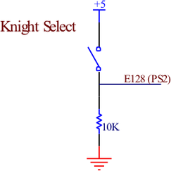
Before game play started, a switch was used to tell the robot which knight to respond to the appropriate game commands.
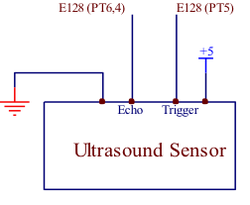
A pair of ultrasonic sensors were used on the front and back of the robot to measure the distance from each wall, respectively. When the robot sensed that it was a certain distance away form a wall, it would begin a deceleration routine.
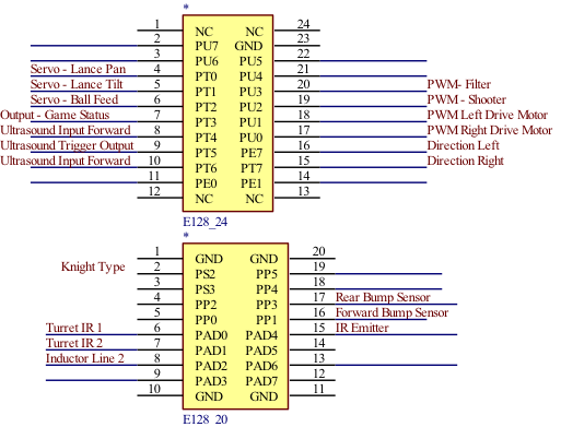
Final pinout diagram of the ‘E128 connectors showing all the inputs and outputs.
